
231-941-0215 sale@namkeenmachine.com 2707 Aero Park Drive Traverse City, MI
Eng
  • Eng
  • Deu
  • Fra

What Is an Energy Storage Connector?

An Energy Storage Connector links battery modules, power-conversion equipment, and control systems. It carries current while maintaining a stable electrical and mechanical interface. Inside a battery cabinet, that may mean a compact, touch-safe connection exposed to vibration, heat, and repeated service work. Small part. Big consequences.

The scale of deployment makes connector design increasingly important. The International Energy Agency’s Batteries and Secure Energy Transitions report says global energy-storage capacity must grow sixfold by 2030, reaching 1,500 gigawatts in its net-zero scenario. That expansion will require connections that support high current, limit resistance-related heating, and remain dependable across demanding operating conditions. A connector is not a substitute for sound system engineering, though. Poor installation or unsuitable ratings can undermine even a well-designed component.

Dr. Imre Gyuk, a longtime U.S. Department of Energy energy-storage program leader, has described storage as “the key to a clean energy future.” The phrase captures the larger purpose, but connectors deserve closer attention than they often receive. Their contact resistance, temperature rise, insulation, and locking method affect practical system performance. Buyers should check manufacturer specifications and test evidence, not rely on appearance alone. A metal housing can look reassuring. It proves very little. This introduction examines what an Energy Storage Connector does, how its key features matter, and what engineers should verify before choosing one. Some details vary by system; that uncertainty deserves honest treatment.
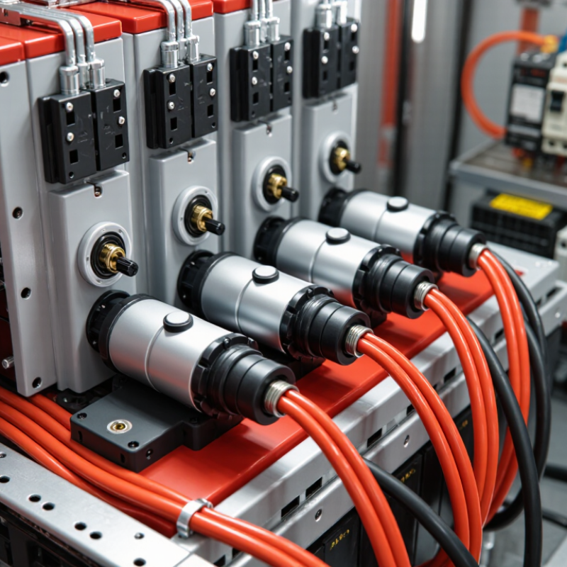
What Is an Energy Storage Connector?

Definition and Core Function of an Energy Storage Connector

An energy storage connector is an engineered electrical interface between battery modules, racks, and power-conversion equipment. It carries direct-current power across a defined connection point. Some designs also transmit monitoring signals or include an interlock circuit. Its core function is to maintain a secure, low-resistance path while keeping live conductors insulated from people and nearby equipment. Small part. Large consequence.

In a battery rack, the connector must match the system’s voltage, current, polarity, and cable size. A loose or poorly seated contact can create heat; damaged insulation can expose hazardous voltage. The IEA’s 2024 Batteries and Secure Energy Transitions report provides a sense of the scale: its net-zero pathway calls for 1,500 GW of global energy storage capacity by 2030, including 1,200 GW of batteries. That forecast does not prescribe connector designs, but it highlights why dependable connections matter across growing installations. A connector is sometimes treated as a simple plug. That assumption deserves a second look: fit, locking, insulation, and clear maintenance procedures all affect how reliably the system operates.

Key Components and Their Roles in the Connection

An energy storage connector joins battery modules, cables, or power conversion equipment while carrying substantial current. Its metal contacts form the electrical path. Contact shape and surface finish affect resistance, heat, and long-term stability. Small details matter. A loose contact can warm under load, even when the outer housing looks undamaged.

The insulating housing keeps conductive parts separated and helps prevent accidental contact. Its shape may also guide correct alignment. Keying features make it harder to mate incompatible connections, while a locking latch helps resist movement from vibration or cable pull. The latch should engage clearly, not just appear closed. At the cable end, a crimp or other termination method connects the conductor to the contact; poor workmanship here can create a hidden hot spot. Seals around the interface help limit dust and moisture, though their protection depends on proper installation and the connector’s rated conditions. Strain relief supports the cable near the termination, where repeated bending can otherwise fatigue the conductor. These parts work as a system. Inspection still has limits: surface checks cannot reveal every internal defect, so connector selection and maintenance should follow the equipment maker’s technical guidance.

Energy Storage Connector: Illustrative Voltage Drop

How to read this chart: Voltage drop is calculated using V = I × R, assuming a constant contact-pair resistance of 0.5 mΩ. This is an illustrative calculation, not a universal connector specification. Actual resistance and current limits depend on the connector design, installation, and operating conditions.

Key components and roles: Conductive contacts carry current; the insulator keeps contacts electrically separated; the housing and locking mechanism align and retain the connection; cable terminations join the connector to the conductors; and seals help protect against environmental exposure where fitted.

How Connectors Link Batteries to Energy Storage Systems

An energy storage connector links a battery module to the cables and equipment that move power through a storage system. It carries current between battery terminals, busbars, and components such as an inverter. The connection must maintain correct polarity and suit the system’s voltage and expected current. A mismatch can cause overheating or interrupt power flow.

The physical details matter. In a battery cabinet, connectors may sit close together, with cables routed through narrow spaces. A secure fit helps resist vibration and reduces the chance of a poor electrical contact. Dust, moisture, or damaged insulation can still create problems. A connector’s rating alone does not guarantee a reliable installation.

Some connectors include locking features or touch-safe housings, which can make handling safer during approved service work. Technicians should follow the system’s instructions and verify that parts are compatible before connecting them. It is easy to focus on the plug and overlook cable size, crimp quality, or strain on the connection. Those details deserve a second look. A tidy cable run is useful, but it is not proof that every contact is sound.

Common Connector Types and Their Differences

Energy storage connectors link battery modules, racks, and power conversion equipment. Their job sounds simple. It is not. They must carry high DC current while limiting heat, resistance, and accidental separation. Contact material, cable size, voltage rating, and installation method all matter.

Bolted cable lugs use a stud and nut to create a firm, serviceable joint. They suit fixed connections, but installers need correct torque and periodic inspection. Plug-in connectors join cables quickly and may include touch-safe housings or polarity keying. They simplify module replacement, though their mating cycles and current ratings must match operating conditions. Busbar connectors join flat conductors directly, saving cable space in compact racks. Alignment matters. Poor contact pressure can create hot spots.

Screw-clamp terminals are common for smaller auxiliary circuits, while heavy battery paths typically need higher-current interfaces. That distinction is easy to miss. A connector that fits physically may still be unsuitable electrically. Compare continuous and peak current, voltage, temperature rise, ingress protection, and cable range with the system design. In a vibration-prone cabinet, a stable bolted joint may be preferable to a convenient plug-in type. But bolted joints are not automatically safer; workmanship matters. Torque checks and thermal imaging can reveal problems that drawings do not.

What Is an Energy Storage Connector? - Common Connector Types and Their Differences
Connector Type How It Connects Typical Use in Energy Storage Systems Main Advantages Key Considerations
Bolted cable lug A crimped or mechanically attached lug is fastened to a stud or terminal with a bolt. Battery terminals, inverter connections, and other high-current cable connections. Creates a robust connection and can accommodate large conductors. Requires correct lug selection, crimping, tightening, and inspection. The joint may need protection against corrosion and loosening.
Bolted busbar connection Conductive busbars are joined directly with bolts, sometimes using a flexible link between components. Battery racks, DC distribution assemblies, and connections between major system components. Provides a compact, low-resistance path for distributing high current. Alignment, contact-surface condition, fastener torque, insulation, and clearance must be managed carefully.
Touch-safe plug-in power connector Mating contacts connect when the plug and socket are fully engaged; designs may include locking features. Removable battery modules and serviceable connections within battery cabinets or racks. Supports faster module installation and removal than a bolted cable joint. Must be rated for the system voltage, current, temperature, and expected mating cycles. Interlocking or de-energized servicing may be required by the system design.
Stud-and-nut terminal A cable lug or busbar is secured to a threaded terminal using a nut and suitable washers. Battery posts, power equipment terminals, and fixed DC connections. Simple, mechanically secure, and suitable for connections that are not frequently disconnected. Correct hardware and tightening procedures are important; exposed conductive parts may require covers or barriers.
Terminal block Conductors are clamped by screws, springs, or another built-in clamping mechanism. Control wiring, monitoring circuits, auxiliary power, and lower-current distribution. Organizes multiple wires and can make inspection or maintenance more convenient. Usually not a substitute for a suitably rated high-current battery connection. Conductor size and terminal ratings must match the application.
Signal or communications connector Small contacts carry control, measurement, or data signals between devices. Battery-management systems, sensors, monitoring equipment, and control interfaces. Separates low-power signals from the main power path and supports organized system wiring. Pin assignment, polarity, shielding, environmental sealing, and separation from power wiring depend on the design.

Safety and Performance Factors in Connector Selection

An energy storage connector joins battery modules, busbars, or power-conversion equipment. Its selection affects heat, voltage drop, and maintenance safety. Match its rated current to the real duty cycle, not just the inverter’s peak figure. Check contact resistance, temperature rise, insulation, polarity protection, and resistance to dust or moisture. A loose contact can create a hot spot; a connector that is difficult to inspect can hide one.

The U.S. Department of Energy’s 2022 Grid Energy Storage Technology Cost and Performance Assessment uses 85% round-trip efficiency for lithium-ion systems. That is a system-level benchmark, not a connector guarantee. Still, connector losses matter: at high current, even modest resistance produces heat through I²R losses. Review test evidence for temperature rise, vibration, and mating cycles; IEC 60512 provides methods for evaluating electrical connectors. One design mistake is judging capacity by cable size alone. It is easy to overlook the contact interface.

Tips: Compare the connector’s continuous-current rating with measured operating conditions. Check that cables are fully seated and strain-relieved. Leave enough space for inspection and safe disconnection. Small details matter. Recheck temperature after commissioning, especially at terminals carrying sustained high current. An oversized connector is not automatically safer if its contacts are poorly matched or assembled.