Choosing the best rotary pump in 2026 starts with the duty, not the catalog. A gear pump may suit steady transfer of clean, viscous oil. A twin-screw model can handle changing flow and some delicate fluids. Lobe and circumferential-piston designs are common options where gentle product handling and cleanability matter. These are starting points, not guarantees. Fluid properties, pressure, temperature, solids, seal compatibility, and cleaning requirements can change the choice.
Energy and lifecycle costs deserve equal attention. The U.S. Department of Energy’s Improving Pumping System Performance: A Sourcebook for Industry reports that pumping systems account for nearly 20% of global electricity demand. It also notes that they can consume 25–50% of the energy used in some industrial operations. Those figures cover pumping systems broadly, not rotary pumps alone, but they show why efficiency and operating conditions matter. Small details matter. A pump running far from its intended duty can bring higher energy use, wear, or maintenance costs. No single pump type wins every application. That sounds simple. It isn’t. This guide compares common rotary pump types by operating principle, suitable fluids, strengths, limitations, and buyer checks, helping industrial teams ask better questions before specifying equipment.
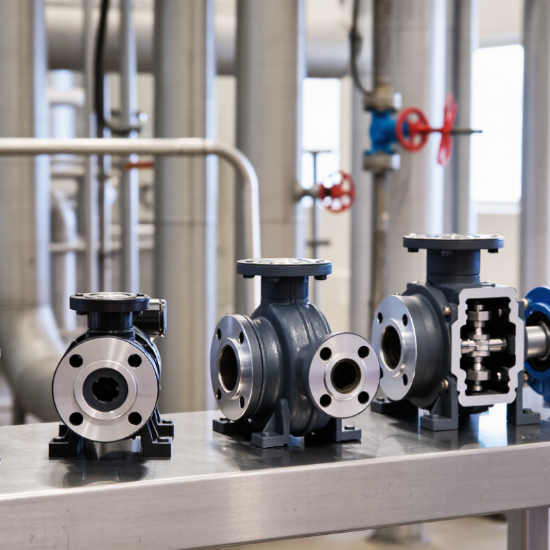
Rotary pumps are positive-displacement machines: each rotation traps and moves a volume of liquid. API Standard 676, Fourth Edition (2022), sets requirements for these pumps in petroleum, petrochemical, and gas industry services. It covers design, materials, inspection, and testing. Common designs include gear, screw, sliding-vane, and circumferential-piston pumps. Their operating principles differ, so “rotary” alone does not tell buyers how a pump will perform. Not every rotary pump meets API 676.
The U.S. Department of Energy’s Improving Pumping System Performance: A Sourcebook for Industry reports that pumping systems account for nearly 20% of global electricity demand, and 25–50% of energy use in some industrial plants. These figures describe pumping systems overall, not rotary pumps alone. Still, they show why efficiency deserves attention. For a real selection, compare viscosity, flow range, pressure, solids content, seal needs, and expected operating hours. A pump that handles thick liquid at startup may not be the best fit across the full duty cycle. That detail is easy to overlook.
Tips:Ask for test data at your actual operating conditions. Check whether the pump can run dry briefly, tolerate entrained air, or handle temperature changes; do not assume it can. Read the API 676 scope and vendor documentation together. Small differences matter.
Rotary pumps move liquid through chambers formed by rotating parts and the pump casing. Gear pumps use meshing gears to carry fluid around the housing. They suit oils and other clean, lubricating liquids, but abrasive particles can wear their close clearances. Small clearances matter. Screw pumps use one or more screws to create steady flow, often with less pulsation than gear designs. They can handle viscous fluids, though startup conditions and speed still affect performance.
Vane pumps use sliding blades that press against the casing, making them useful for relatively clean liquids and changing flow demands. Lobe pumps move fluid between rotating lobes without the lobes touching, which can help when gentle handling matters. Their larger passages may tolerate some solids, but clearances still need protection. Progressive-cavity pumps use a rotating helical rotor inside an elastomeric stator. They can move thick, shear-sensitive fluids and suspended solids, but dry running may damage the stator. Not always obvious. A selection chart may overlook cold-start viscosity, abrasive wear, or cleaning requirements. Buyers should compare the actual fluid, temperature, pressure, and maintenance conditions—not just the pump category.
| Pump Type | Operating Principle | Best-Suited Fluids | Solids Handling | Flow and Pressure Characteristics | Key Advantages | Main Limitations | Typical Industrial Uses |
|---|---|---|---|---|---|---|---|
| Gear | Meshing gears trap liquid between the gear teeth and casing, carrying it from the inlet to the outlet. Designs include external- and internal-gear pumps. | Clean or lightly contaminated oils, fuels, lubricants, resins, and other fluids. Many models suit medium-to-high viscosities. | Generally low tolerance. Hard particles can cause wear, damage clearances, or jam the pump. | Steady, predictable flow; flow typically rises with speed. Can generate substantial differential pressure, depending on design, speed, and fluid viscosity. | Compact construction, simple operation, and good performance with lubricating, viscous liquids. | Close clearances require suitable filtration and adequate lubrication. Flow can slip internally, especially with thinner fluids or increased pressure. | Oil transfer, lubrication systems, fuel handling, polymer processing, and metering of compatible liquids. |
| Screw | One or more rotating screws move liquid axially through the pump. Multiscrew designs differ in rotor arrangement and whether the pumped liquid lubricates the rotors. | Oils, fuels, hydraulic fluids, and other clean liquids across a broad viscosity range. Some configurations are designed for multiphase service. | Usually limited for abrasive solids; allowable contamination depends strongly on screw geometry and clearances. | Typically smooth, low-pulsation flow. Pressure capability and flow range depend on the number of screws, construction, speed, and service conditions. | Quiet operation and relatively low pulsation; well suited to continuous transfer of compatible liquids. | May require careful alignment, material selection, and protection from dry running or abrasive contamination. | Fuel and oil transfer, marine systems, power generation, and selected process or multiphase applications. |
| Vane | Sliding vanes in a rotating rotor form changing-volume chambers that draw in and discharge liquid. | Clean, lubricating liquids such as fuels, oils, and solvents where materials and seals are compatible. | Low tolerance for abrasive particles, which can accelerate vane and casing wear. | Generally smooth flow. Capacity can vary with speed, and some designs offer useful self-priming capability; pressure limits are model-specific. | Compact design, reliable transfer of compatible liquids, and good suction performance in suitable installations. | Vanes are wear components. Dry running, poor lubrication, or abrasive fluids can shorten service life. | Fuel transfer, vehicle and equipment systems, solvent handling, and low-to-moderate-pressure liquid transfer. |
| Lobe | Two or more non-contacting lobed rotors move fluid in cavities between the rotors and pump casing. | Viscous, shear-sensitive, or hygienic-process fluids, including many food, beverage, pharmaceutical, and personal-care products. | Can pass some soft particles or larger inclusions when designed with appropriate clearances; abrasive solids remain challenging. | Positive-displacement flow with pulsation that may be noticeable, particularly at lower lobe counts or higher speeds. Pressure capability is design-dependent. | Non-contacting rotors can reduce product damage; many designs allow cleaning and inspection for sanitary service. | Clearances and seals need careful selection. Abrasive wear and operation against a closed discharge can damage the pump. | Food and beverage processing, hygienic transfer, viscous product handling, and selected slurry duties. |
| Progressive Cavity | A helical rotor turns inside an elastomeric stator, creating sealed cavities that progress along the pump as the rotor rotates. | Viscous, abrasive, shear-sensitive, and solids-bearing fluids, subject to rotor, stator, and elastomer compatibility. | Often handles suspended solids and slurries better than close-clearance gear or vane designs; particle size and concentration must be checked against the specific pump. | Low-pulsation, nearly proportional flow at a given speed. Can develop high pressure, often using stages; pressure limits depend on construction and service. | Suitable for challenging, viscous, or solids-laden media; flow is readily controlled by changing speed. | Stator elastomers require chemical and temperature compatibility. Dry running can rapidly damage the stator; wear may reduce performance. | Wastewater sludge, mineral and industrial slurries, food products, and chemical or process-fluid transfer. |
Selection note: Performance and material compatibility vary by pump construction and operating conditions. Confirm viscosity, temperature, solids content, suction conditions, required flow, and differential pressure with the applicable pump documentation before selection.
Rotary pumps serve different duties, even when their flow rates look similar on paper. Gear pumps suit steady, clean liquids and compact installations. Screw pumps can deliver smooth flow at higher capacities, while lobe pumps handle some shear-sensitive products. Vane pumps often work well with thinner fluids. Progressive cavity pumps can move thick mixtures with suspended solids.
Flow is only one part of the selection. Check the required differential pressure at the actual operating speed, not just the pump’s maximum rating. A thick fluid may reduce slip in a gear pump, but it also raises starting torque. Measure viscosity at operating temperature; a cold morning can change the load sharply. Small detail. It matters.
Solids-handling duty depends on particle size, shape, concentration, and clearances. Soft fibers may pass through a lobe pump, while abrasive grit can accelerate wear in close-clearance designs. Progressive cavity pumps tolerate many solids, but dry running can damage the stator quickly. This is where selection gets messy. Buyers should compare test data using a fluid close to the real process, then review wear parts, speed limits, and maintenance access. I would not rely on a single catalog curve for a fluid that changes with temperature or batch.
Before choosing a rotary pump, confirm the hazardous-area classification at its installation point. Zone 0 means an explosive gas atmosphere is present continuously, frequently, or for long periods. Zone 1 means it is likely during normal operation. Zone 2 means it is unlikely, and lasts only briefly if it occurs. These definitions shape equipment selection; they do not identify a pump type by themselves.
For gas hazards, ATEX equipment categories commonly align as 1G for Zone 0, 2G for Zone 1, and 3G for Zone 2. Check the marking against the gas group, temperature class, ambient conditions, and required protection concept. A pump’s motor may be certified while nearby instruments, seals, or electrical connections are not. Check the whole assembly. Small gaps in documentation can become expensive surprises.
Ask suppliers for certificates and operating limits for the complete installation, including coupling guards and any monitoring devices. Confirm the pumped liquid cannot create a separate ignition risk through leakage, static charge, or excessive surface temperature. Details matter. A duty cycle that looks routine on paper may alter heat buildup in practice. Have a competent hazardous-area specialist review the classification and final equipment schedule before purchase; procurement teams sometimes focus on the pump alone, and that is an easy assumption to miss.
For gas or vapour atmospheres, the minimum ATEX equipment category is 1G for Zone 0, 2G for Zone 1, and 3G for Zone 2. Higher-protection categories may also be suitable in less demanding zones. A rotary pump type alone does not establish ATEX suitability: verify the certification and marking for the complete pump assembly, including its drive and accessories, against the site’s gas group, temperature class, and operating conditions.
Industrial buyers comparing rotary pump types should verify duty conditions against API 676, not rely on a pump label. API 676 covers rotary positive displacement pumps for petroleum, petrochemical, and gas industry services. The U.S. Department of Energy’s 2006 Improving Pumping System Performance: A Sourcebook for Industry reports that pumping systems use nearly 20% of global electricity, and 25–50% of energy in some industrial operations. That scale makes avoidable recirculation and oversized motors worth challenging.
Check flow, differential pressure, speed, viscosity, and relief-valve settings against the real operating range. Request an NPSH calculation at minimum tank level and cold-start viscosity; suction-line losses can erase the apparent margin. Confirm seal arrangement, flushing needs, and elastomer compatibility with the fluid, temperature, and solids. Match wetted metals to corrosion data, not habit. I would question any quote that omits these conditions.
Tips: Ask for API 676 documentation, performance data, and a seal and materials schedule. Compare NPSH available with the supplier’s required value at worst-case conditions, including acceleration losses. Keep one uncertainty visible: field viscosity may differ from the lab sample.